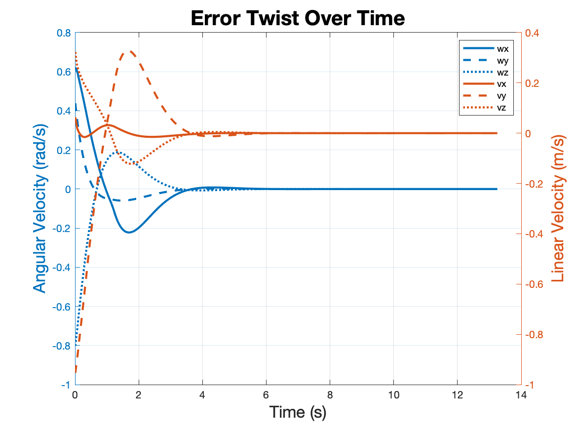
KUKA YouBot is a 5 revolute joint robot arm attached to an omnidirectional platform, fitted with 4
mecanum wheels. The mobile robot is equipt with a gripper end effector that enables it to pick up and
manipulate objects.
In this project, I developed control code to map and execute movement of the robot in order to pick up a
cube
and move it to a predefined location.
Utilizing Euler's Method, this script determines the next state of the robot and all of its elements
based on
the joint velocities. Through spatial twists, velocities are calculated and displacements are applied to
achieve the next state.
For this particular project, the time step was set to be every one hundredth
of a second. As a test, robot simulation was calculated for movement in the +X, +Y, and rotation
about the vertical with different wheel velocities.
The trajectory of the gripper end effector is calculated based on starting, cube, and end
placement transformation matrices. This portion of the code calculates the reference configuration
matrices
of the end effector in order to pick up and place the cube.
As a test, the transform matrices were calculated at each time step of the process and graphically
demonstrated
in CoppeliaSim.
The feedforward controller takes the reference configurations from the Trajectory Generator code and
determines the velocity twist at each time step. Error is found by comparing to the actual robot
configuration,
found via the Kinematics Simulator code. A PD controller is implented to minimize error between
the reference and actual configurations.
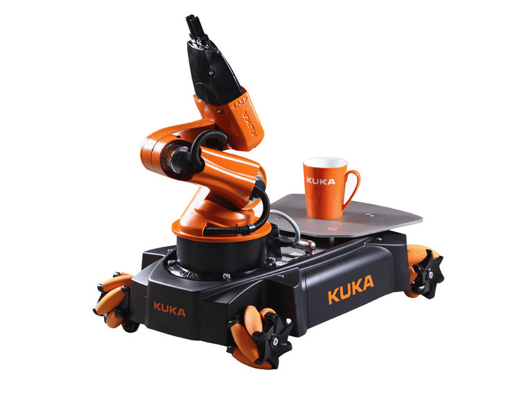
In the plot to the right, a very poorly tuned PID controller is implemented, showing terrible overshoot
and
settling time.
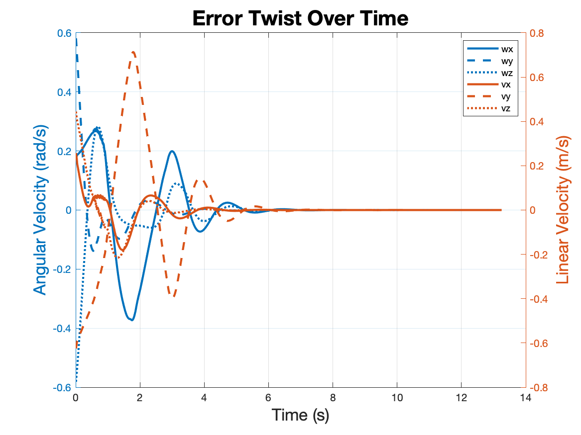
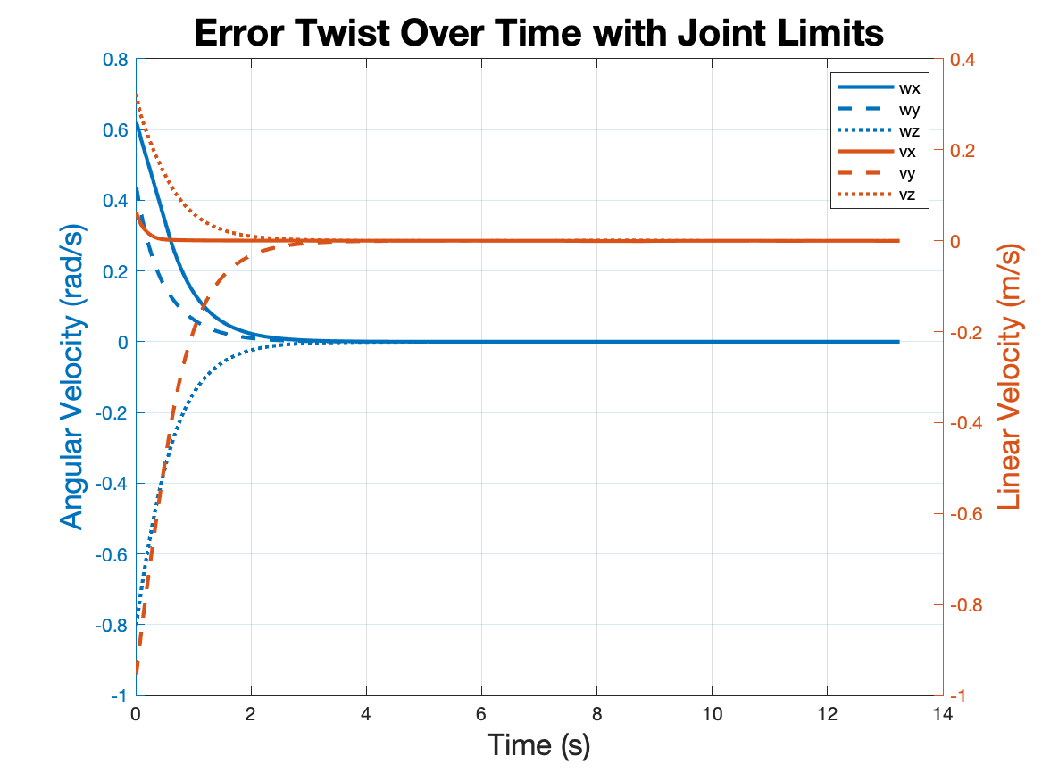
Implementing a Well Tuned Controller
A PD controller was implemented to minimize error in the configuration sequence. Integeral
gain was not needed in this ideal simulation which already showed no steady-state error with
PD
control. The final proportional and derivative gains minimized error before the first
trajectory was complete. To verify the controller, an initial starting configuration was
set with at least 30 degrees of orientation error and 0.2 meters of positional error from
the assumed starting configuration.
Compared to a Poorly Tuned Controller
To show the effectiveness of the implemented controller, a poorly tuned PID controller was
visualized. The goal was to set gains that could still achieve the task, but with large
oscillations and settling time. As shown in the error plot and the simulation, the robot
greatly overshoots its desired trajectory and has to apply excess power to stay on course.
The application of unnecessarily large integral and proportional gain led to greater
instability in the system.
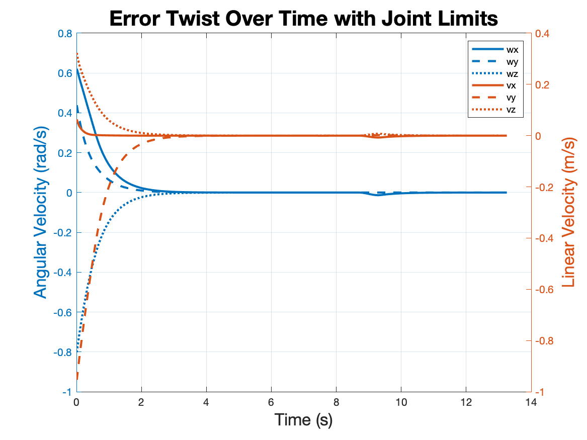
Integrating Joint Limits to Avoid Self-Collision
After testing a few cases, some trajectories caused the robot to collide with itself and
the environment. To avoid such collisions in the physical world, joint limits were set to
limit motion in the robot arm. In the code, when joint velocities are calculated, joint
angles are checked against the set limits. If a joint limit is exceeded, the column in
the kinematics Jacobian matrix is set to zero and velocities are recalculated. This
essentially forces the robot to utilize other joints to achieve the desired end effector
velocity.
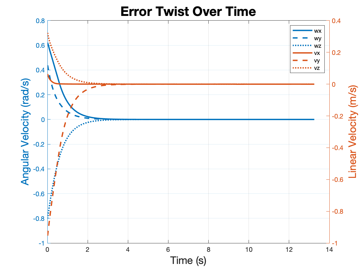
Applying to a Different Test Case
For a final test, the well-tuned PD controller and joint limit modifier were applied to a
new case with a different cube start, cube end goal, and robot start configurations.
The actual robot was also configured to start with at least 30 degrees of orientation
error and 0.2 meters of positional error from the assumed starting orientation.
Successfully, the control code was able to set a path for the YouBot to still achieve its
goal of moving the cube from one orientation and position to another.